The Pico-Sketch application is an etch-a-sketch like game running on the Raspberry Pi Pico using the Pimoroni Pico-Display as the user interface.
Why does the world need 1.14″ digital etch-a-sketch? Well it doesn’t ?. I created this project to demonstrate that building a functional simulator for an embedded application can be a straight forward and relatively quick task. I was able to create the simulation infrastructure and the Sketch application in 4 calendar days. Granted this is not my first time doing this — YMMV.
What is a functional simulator?
The goal of a functional simulator is to execute the production source code on a platform that is not the target platform. The simulator should provide the majority of the functionality (but not necessarily the real-time performance) of the application. In most cases, this hardware platform is a personal computer running Windows or Linux.
Why a functional simulator? Two primary are reasons:
- Hardware is always late. By having a functional simulator your firmware is no longer gated/blocked by the availability of hardware.
- Development is faster. Compiling, executing, and debugging on a PC is much faster — and typically using much better tools — then compiling, flashing the executable, and debugging on the target.
To illustrate how much of the application is platform independent vs target hardware independent — the following code snippets are for the target hardware specific code, i.e. the rest of the application is platform independent. There are no conditional compile statements (with respect to the platform) in the application code.
int main( void )
{
 // Initialize CPL
 Cpl::System::Api::initialize();
 // Initialize the board
 Bsp_Api_initialize();
 platform_initialize_buttons();
 // Start the Console/Trace output: Accepting the default UART Config parameters, e.g. 115200, 8N1
 Cpl::System::RP2040::startConsole();
 Cpl::System::RP2040::getConsoleStream().write( "\n**** APPLICATION START-UP *****\n" );
 Cpl::System::RP2040::getConsoleStream().write( "Cpl and the Bsp have been initialized.\n" );
 // Set the stream of the console
 g_consoleInputFdPtr  = &(Cpl::System::RP2040::getConsoleStream());
 g_consoleOutputFdPtr = &(Cpl::System::RP2040::getConsoleStream());
 // Start the application
 runApplication();         // This method should never return
 return 0;
}
// Display driver
pimoroni::ST7789 st7789_( MY_APP_DISPLAY_WIDTH, MY_APP_DISPLAY_HEIGHT, pimoroni::ROTATE_0, false, get_spi_pins( pimoroni::BG_SPI_FRONT ) );
void platform_updateLcd( pimoroni::PicoGraphics& graphics )
{
 st7789_.update( &graphics );
}
void platform_setLcdBacklight( uint8_t value )
{
 st7789_.set_backlight( value );
}

static Driver::LED::PimoroniPico::RedGreenBlue rgbLEDDriver_( APP_LED_RGB_R , APP_LED_RGB_G, APP_LED_RGB_B );

Driver::LED::RedGreenBlue*                     g_rgbLEDDriverPtr = &rgbLEDDriver_;

Driver::Button::PolledDebounced g_buttonA( { APP_BUTTON_A_PIN_NUM, true } );
Driver::Button::PolledDebounced g_buttonB( { APP_BUTTON_B_PIN_NUM, true } );
Driver::Button::PolledDebounced g_buttonX( { APP_BUTTON_X_PIN_NUM, true } );
Driver::Button::PolledDebounced g_buttonY( { APP_BUTTON_Y_PIN_NUM, true } );

void platform_initialize_buttons()
{
 driverButtonHalRP2040_initialize( g_buttonA.getHandle() );
 driverButtonHalRP2040_initialize( g_buttonB.getHandle() );
 driverButtonHalRP2040_initialize( g_buttonX.getHandle() );
 driverButtonHalRP2040_initialize( g_buttonY.getHandle() );
}
Anatomy of the Simulator
The Pico-Sketch application uses a loosely coupled design to separate the bulk of the source code from the target platform. Specifically the following items need to be decoupled:
- The Pico C/C++ SDK.
- The 1.14″ LCD display and back-light control
- The RGB LED
- The 4 momentary push buttons
Pico C/C++ SDK
The Pico-Sketch application is built on top of the Colony.core C++ library (included as part of this repository). Part of the library provides an OSAL layer that decouples the application from the Pico’s C/C++ SDK including threading support for the Pico’s dual cores. The library also provides the concrete Windows implementation of the OSAL.
Note: The Colony.core library is existing functionality and as such was not considered as part of the time/effort it took to build the functional simulator.
LCD Display and Backlight
A choice was made to simulate the display as a separate executable. This separate executable would implement the simulated display as bit map image and the Pico-Sketch application would provide the raw pixel data for the bit map. The two executables communicate via TCP sockets.
The simulation of the display is done at the SPI driver level. The Pimoroni display hardware comes with a set of C++ libraries for using the display. Their graphic engine has a frame buffer where all draw operation occurs. This frame buffer is exposed/provided to a Pimoroni supplied SPI driver that in turns transfer the data to the external LCD Controller IC. For the simulation, the frame buffer is provided to a simulated driver that transfers the frame data contents to the Windows application via sockets.
The back-light feature was not simulated because the application does not allow the user the change the brightness of the display (i.e. no return on the investment to simulate). However, an abstraction is still required in the Pico-Sketch application to support the application code to not have conditionally compiled code.
RGB LED
The simulated the RBD LED was implemented as 10×10 bit map image in the GUI application where the Pico-Sketch application would send the RGB color encoding for the pixels in the bit map. The transfer of the LED color information is done via the same socket connection used for the display data.
The Pimoroni supplied C++ Libraries provide a set of methods for setting the color of the LED using RGB or Hue/Saturation/Value encoding as well as for controlling the brightness of the LED. The choice was made to create a C++ abstract interface that allows clients to set the color (both RGB and HSV encoding) and brightness of an RGB LED. Two implementations of this abstract class were done — one using the Pimoroni interface and one for the simulation.
Push Buttons
The 4 momentary push buttons are simulated using button widgets in the GUI executable. Press and release events from these button widgets are sent to the Pico-Sketch application via the same socket connection used for the display data.
The Pimoroni supplied code has a C++ class/interface for buttons. The class does not add much functionality over what is supplied by Pico C++ SDK, except for type-o-matic functionality (e.g. key repeat events) when a button is pressed and held down. The class did not provide any de-bouncing of the raw key inputs.
The choice made in this case was to create a concrete target independent button driver that defines a Hardware Abstract Layer (HAL) that allows it to be used on multiple platforms. The concrete driver provides de-bouncing of the raw button inputs as well as the typo-o-matic feature. Two implementations of the HAL layer are done — one using the Pico C++ SDK for button GPIO and one for the simulation. Note: because the driver is target independent it can have an automated unit test that verifies its logic (this is on my TODO list).
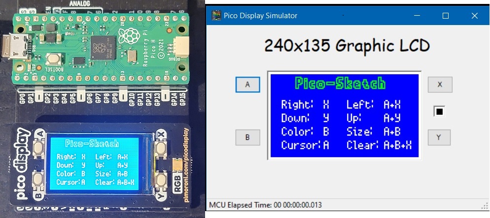
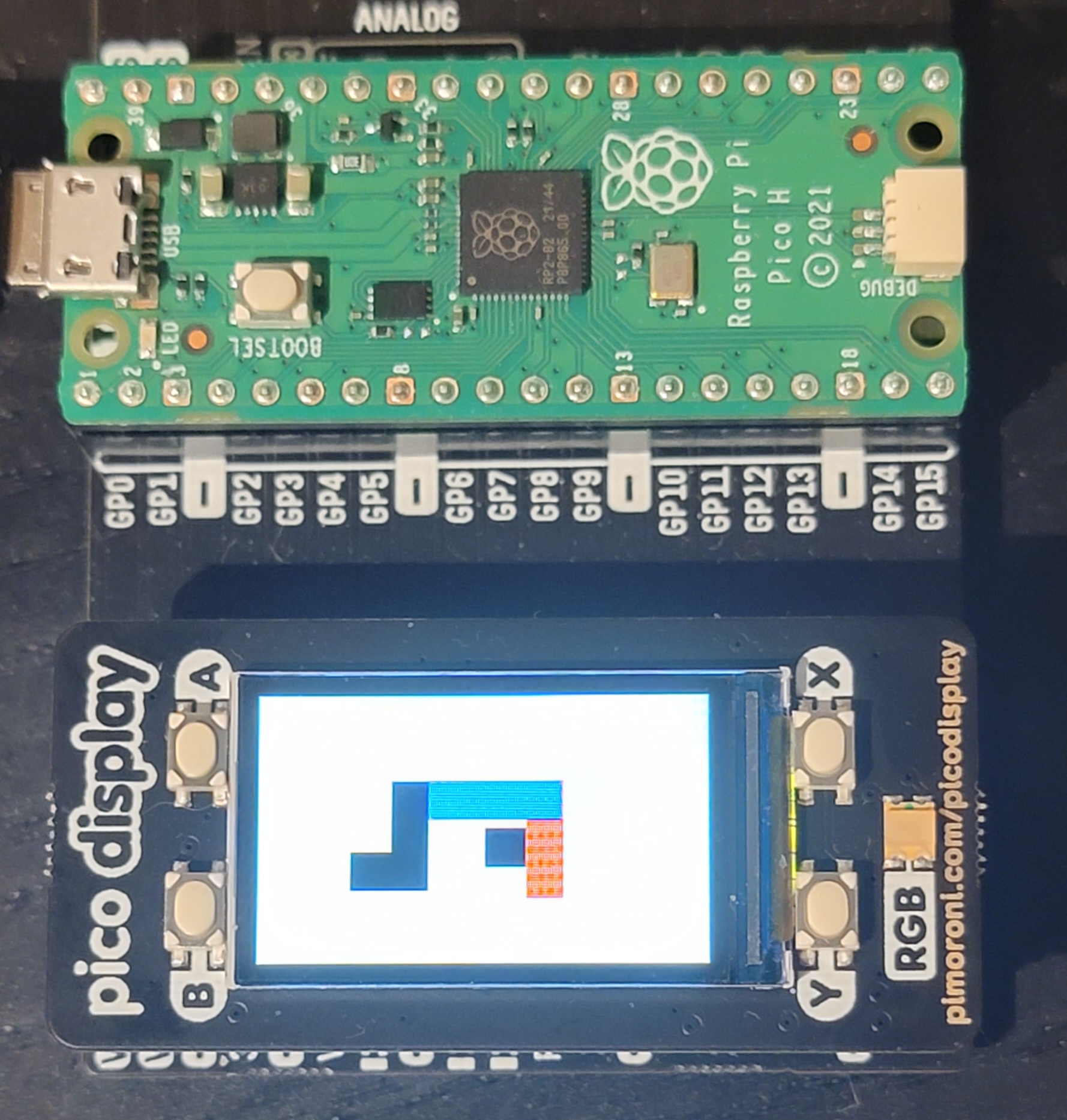
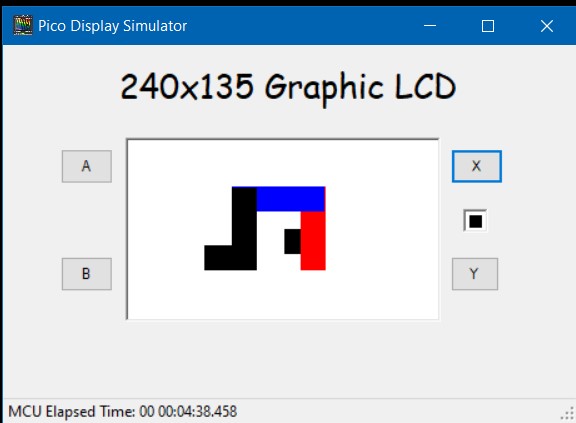
Outcome
Here are some photos/screen shots of the Pico-Sketch running on the hardware and on the functional simulator
The Devil is the Details
When I first started working on the simulator I had naively assumed that since the Pimoroni Graphic library had no dependencies on the SPI driver that the library was target independent. I was wrong. The header files in the Pimoroni graphic library has #include statements to the Pico C++ SDK. And there is a dependency on a GCC compiler specific header file (sys/cdefs.h). Fortunately the graphic library has no link time dependencies on the Pico C++ SDK or the GCC compiler. This allowed me to ultimately be successful in creating the Pico-Sketch application that runs on a Windows box. But it prevented me from using the Visual Studio compiler. I had to use the Mingw compiler. The downside of not using the Visual Studio compiler is not using Visual Studio for debugging. I have to use GDB. Let’s just say my GDB skills are poor at best and I am too cheap to pay for the GDB plugin for Visual Studio.
This is a morality tale about the evils of including header files in your header files that are not need for the content of the including header file.
Exercise left to the Reader
For more details about functional simulation and how to make it part of a firmware design/project — I recommend the following book: Patterns in the Machine: A Software Engineering Guide to Embedded Development